(5) Establish a solid cube as described in (1). The upper and lower mold parting surfaces are divided into two parts, and the inverse mold of the mold outer mold obtained in (3) is used. As a tool entity, the corresponding half of the cube body is taken as the target entity, and the Boolean subtraction operation is performed to obtain the initial prototype of the model on the external model and the model (see Figure 5).
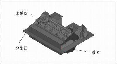
Figure 5 Upper and lower models
Third, the formation of the upper and lower templates and the simulation test of the mold
The upper and lower models generated by the Boolean operation are typeset according to the specifications and connection methods of the modeling device, and the tooling connection portion is made. Install the exhaust column of different numbers and sizes in the appropriate part of the mold according to the requirements of the molding process (see Figure 6), and add the core forming block (see Figure 7) and the sand core exhaust column in the joint with the combined sand core. In this way, the mold model for production application can be obtained (see Figures 6 and 7).
As can be seen from the above description, both the modeling die and the sand core die are obtained from the same casting model, and the corresponding accuracy of the internal cavity and the external shape is very high (accurate to 0.001 mm or more), thus The precise parameter conversion of the outer surface of the casting and the internal cavity on the mold and the reasonable distribution of the inner cavity core are realized.
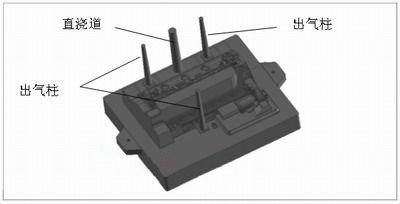
Figure 6 on the template

Figure 7 template
Similarly, the upper and lower templates are operated by Boolean subtraction to form upper and lower cavities (see Fig. 8 and Fig. 9).
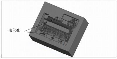
Figure 8 upper cavity
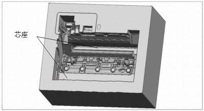
Figure 9 lower cavity
Previous page next page