ã€
Abstract 】This paper introduces the application of I-DEAS software in the processing of planar cam groove, and illustrates the role of the software in CNC machining through specific examples.
I-DEAS software is an integrated software system including computer-aided design, manufacturing and engineering analysis (CAD/CAM/CAE) introduced by UGS in the United States. It has many modules and powerful functions. The software uses the main model technology and the more advanced variable modeling system in the CAD field, providing a complete solution and strong technical support for the enterprise new product development. The application of I-DEAS can improve product quality, shorten product development cycle and create economic benefits for enterprises.
Generative machining is a processing module integrated with I-DEAS software. This module provides 2.5 to 3 axis milling, 4 to 5 axis machining and turning. Each machining method has a variety of machining strategies. select. Generative machining not only directly processes curves, surfaces and solids designed by the I-DEAS software modeling module, but also NC programming of parts generated by other CAD systems imported via the data interface. According to the characteristics of the workpiece, the programmer selects the appropriate machining method to generate the tool path, and then compiles the generated tool path through the C-Post universal post-processing program provided by the software, and obtains the machining program for different CNC machine control systems, and then passes The DNC program transfer software is transferred to the CNC machine for processing. Utilizing the powerful functions of the I-DEAS software, Xuchang Tobacco Co., Ltd. carried out three-dimensional modeling of various shaped parts used on the hood equipment, designed the tool path, generated the machining program, and successfully trialed the VCP1000 high-speed milling machine imported from Switzerland.
First, the problems found in the software application process
Xuchang 烟机's P70 cigarette machine has a kind of flat cam groove parts, as shown in Figure 1.
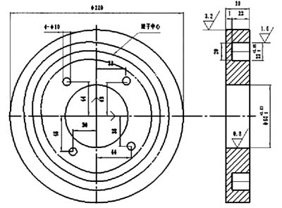
Figure 1 Plane cam groove part of P70 cigarette machine
The center track of the roller is given by the polar coordinates. The drawing requires the roller to move smoothly in the cam groove, but the drawing only gives the coordinates of 36 points. Because the interval is too large, these points can not accurately reflect the movement law of the cam roller, thus resulting in Processing cannot be performed. To solve the problem that the contour control point interval is too large, it is necessary to interpolate between the 36 coordinate points for refinement, but it is found through calculation that if the spacing between the two interpolation points is 0.5 mm, nearly 400 points are inserted. The amount of calculation is large and the way of interpolation between points cannot be determined. To this end, we used the MasterCAM software to collect nearly 400 coordinate points:
1. Constructing a cam profile
36 coordinate points are input by constructing points, and the input 36 points are connected by a spline curve.
2. Create a 2D contour tool path
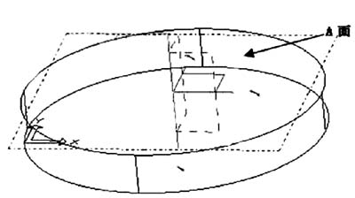
Figure 2 generates the base entity
Next page