(2) The beginning and size of the cold extruded blank. The blank is a 50 mm non-standard copper tube with a contact arm of 33 mm × 162 mm, as shown in Figure 3. On the basis of the extruded product, the diameter is 0.3-0.5mm, which is convenient for the blank to be placed in the cavity. Due to the influence of material flow and cross-section stress during the cold extrusion process, the end faces are especially 34 mm end faces. The bump is uneven, so the machining capacity of 2 mm is left, and the compact amount is taken at 11%. The copper pipe of this specification can be customized at the copper processing factory at the same price.
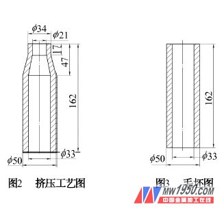
2. Analysis <br> <br> cold extrusion process of the part cross-sectional reduction rate ε = 47.5%, by Now: allowable degree of deformation of non-ferrous metals εf = 90% ~ 95%, extruded at once; P = 2670 KN Use 3150 KN four-column hydraulic press.
3. Mold Structure and Characteristics <br> <br> mold structure shown in FIG. The upper mold is fixed on the movable beam of the hydraulic machine with a pressure plate. The fixing plate 4 and the upper pad 2 are fixed to the upper plate by a 3-M12, 3-12 mm cylindrical pin. The punch is matched with the fixing plate by H7/k6, and the lower end of the punch 3 is machined (34×15) mm mandrel introduction hole. The lower die is fixed to the hydraulic machine table with a pressure plate. The die sleeve 9 and the die 8 are hot-mounted, the interference is 0.3 mm, and the inclination is 1.5°. The mandrel 6 takes a taper of (1/6) ° to facilitate separation from the workpiece 7, surface polishing, surface roughness value Ra = 0.8 μm, and automatically corrects the center in the die. The lower end face is positioned by the ram 11 .
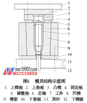
The ejector 11 processes two steps of (21×3) mm and (34×5) mm. When the hydraulic cylinder is working, the 21 mm portion of the ejector pin first pushes the movable mandrel out of the workpiece by 3 mm. At this time, the workpiece Separated from the mandrel; continue to move upwards, the 34 mm portion of the ram pushes the workpiece out of the die, and the length of the ram is matched according to the height of the hydraulic top cylinder.
Previous page next page