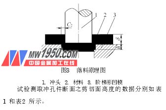
2. The principle test test adopts ordinary presses of 100kN and 250kN respectively. The punched material is pure aluminum plate and brass plate with thickness of 4mm. The punching clearance is taken as C1=(2%~10%) δ, C2=(2.5% ~20%) δ, workpiece size D=20mm. The test die is a general punching die, and several stepped punches and stepped die are respectively manufactured, and respectively tested with ordinary punching punches and die.
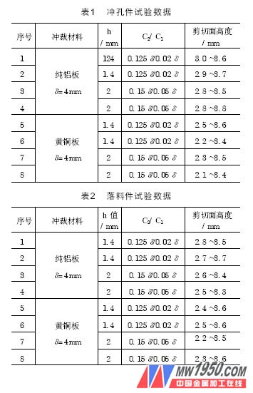
The data of the shear plane height of the cross section of the punching piece are shown in Table 1 and Table 2, respectively.
Compared with ordinary blanking, that is, the same blanking conditions (material, material thickness, press), when C is 0.1 δ, the shear surface height of pure aluminum sheet material is <1.5mm, and the shear surface height of brass sheet material is <1.0. Mm. The test results show that the new blanking process is obviously much higher than the shearing surface obtained by the ordinary blanking process. Regardless of punching and blanking, the shearing surface height is greater than half of the material thickness, and the cross-section photo of the brass plate workpiece Referring to Figure 4, in order to achieve the purpose of improving the shear plane on the basis of conventional blanking. During the test, it was found that when the C1 is small, the shear plane height of the workpiece of the process test is not uniform, and the difference is large. If the gap C1 is enlarged from 2% to about 7.5%, and the gap C2 is enlarged accordingly, a more uniform shear plane is obtained, and the shear plane height is still greater than half of the material thickness.

3. Production test
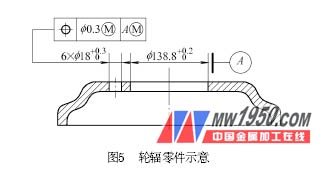
An automobile rim spoke produced by Jiangling Motors Group, as shown in Figure 5, has a large hole size of 138.8 + 0.20 mm, a material thickness of δ = 6 mm, and a material grade of S δ 37 - 2. When the original process and the original punching large hole die are processed, the large hole shearing surface is only about 1.5 mm, which is lower than the 2 mm required for the pattern. Using a pair of old punching punches that have been replaced in production, the working edge of the original straight punch is machined into a step shape on both ends according to the new principle, and its size and shape are shown in Fig. 6. The modified punch is placed in the original punching die and placed on the original press, twice in succession.

Previous page