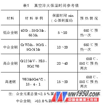
3 quenching heating time. As shown in Fig. 4, T3 is the quenching heating time. In fact, T3 contains two parts. The DF section is the temperature rise and the blistering time of the heated workpiece. The FG section is the holding time of the heated workpiece core to the temperature, that is, the alloying time. . The temperature rise and the venting time are related to the size of the workpiece to be heated, the method of furnace loading (bulk, bundling, dense stacking, etc.), and have little to do with the composition of the workpiece to be heated; the holding time (alloying time) is only related to the composition. The temperature rise and the blistering time can be estimated by the empirical method. At this time, the color of the hearth is “yellow-white†color, and the observation method is the same as before. It is particularly pointed out that the quenching heating rate is significantly accelerated, and the temperature rise and the blistering time are significantly shortened. For the heat retention time (alloying time) after heating and ventilating (that is, the "yellow-white" color is uniform), please refer to Table 1.
The observed color method is more accurate and reliable, and the heating effect and efficiency can be taken into consideration. However, it requires extensive experience in pre-furnace operation and the corresponding basic knowledge of metal heat treatment, and the observation is hard.
Second, the hardness after vacuum heat treatment
1. Vacuum heat treatment parameters of common die steel and hardness after treatment
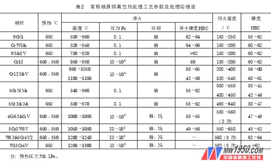
Hardness is an important technical index for the heat treatment of mechanical parts. It is related to the composition and structure of the steel parts of the parts, and also related to many characteristics such as the pressure in the vacuum furnace during the execution of the heat treatment process. Table 2 describes the vacuum heat treatment process parameters and hardness of the common die steel.
2. Effect of quenching oil surface pressure on quenching hardness during cooling in vacuum furnace
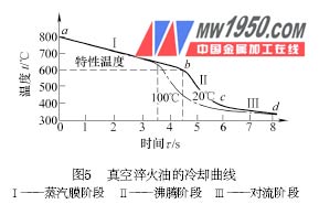
The high temperature workpiece after oil injection can be cooled by three stages of steam film, boiling and convection, as shown in Figure 5. The cooling capacity of the vapor film stage (I) is the worst, the quenching oil surface pressure is too small, the vapor film is not easily broken, and the time in this stage is long, so that the cooling ability of the oil is weak, and the hardness of the workpiece is easily insufficient. In order to obtain sufficient quenching hardness, the quenching oil surface pressure in the vacuum furnace should reach 8×10 Pa 2 to 3 s after the workpiece is filled with oil.
3. Transfer time of the workpiece from the heating chamber to the quenching oil tank in the vacuum furnace
In the double chamber vacuum oil quenching furnace, after the heated workpiece is quenched and heated, the time from the exit of the heating chamber to the quenching oil tank of the cooling chamber is called "transfer time". The time should be as short as possible, such as titanium alloy, beryllium bronze and the like, the transfer time must be <10s. However, too short transfer time will cause accidents such as shaking, collision and dumping of high temperature workpieces; too long will cause small pieces at the edge of the basket, or the sharp corners of the workpiece, and the thinness of the thin part, resulting in insufficient quenching hardness, so the national standard stipulates the transfer. Time ≤ 20s. Despite this, the phenomenon of insufficient quenching hardness of small pieces still occurs from time to time, and the overcoming method is to properly install the furnace.
4. Reasonable furnace loading method
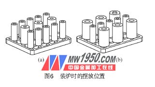
When radiant heating, the heat transfer can only be carried out along a straight line, so that some workpieces are easily blocked and shielded when receiving heat from the heating element. When the vacuum furnace is heated, when the diameter or thickness difference is large, the large workpiece must be placed at the edge, and the small workpiece is placed at the core. For example, Figure 6a is wrong and Figure 6b is correct. When the furnace is layered, the small, thin and thin workpieces are installed in the middle core, and vice versa in the upper, lower or edge, in order to achieve uniform heating as much as possible.
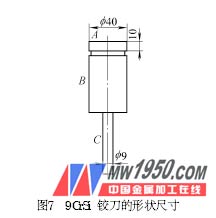
5. Examples
The 9CrSi reamer (the shape of the workpiece is shown in Figure 7) is evenly distributed on the tooling in the vacuum furnace, with more than 40 pieces. Process: 650 ° C 60 min, 870 ° C 40 min into the oil. Hardness requirements are 59 to 61 HRC. The measured results of hardness after treatment were: 59 HRC at A, 42 HRC at B, and 60 HRC at C.
Previous page