3.3 Inverter parameter design steps
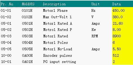
(1) Set the motor parameters to the inverter for dynamic auto-tuning of the motor. In order to play the high performance of the VE series inverter, accurate motor parameters are the basis. First fill in the basic parameters to the relevant position of the inverter:
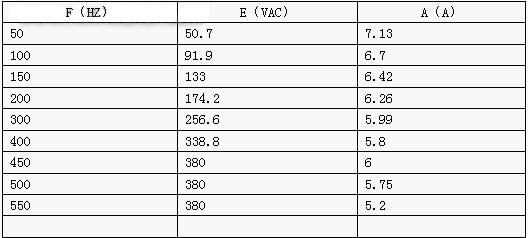
And use the above parameters for VF control operation, the specific situation is as follows, after observing to meet the motor operating characteristics.
(2) Solve an interesting engineering problem. In the above data, the motor rated speed 05-03 is not provided by the motor manufacturer nameplate, and it is not very clear to ask the motor manufacturer. In this case, since the motor itself has an encoder, the inverter is operated to 450hz through VF control, and the r state provided in the inverter is observed. The actual motor speed is about 8900 rpm, and the measured data is filled in 05-03. The rated current of the motor is 25A, 075V43A-2. The rated current of the inverter is only 18A. Therefore, the motor rated current can only be adjusted to the maximum (maximum 21.6A) and filled in the 05-01 parameter.
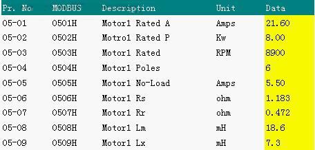
Set the parameter 5-00 to 1 and press the panel "RUN" for dynamic tuning.

After tuning, the motor parameters are
The 11-01 parameter is related to the choice of the encoder direction. If the setting is not correct, there will be a problem with the PG closed loop control. If the setting of 11-01 is correct, it can be observed through the r state of the inverter panel. If r is positive, the direction setting is correct. If it is negative, the direction setting is reversed.
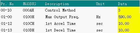
(3) Change the control mode to foc+pg, and adjust the maximum operating frequency and acceleration and deceleration time.
Previous page next page