Oil pump flexibility test requirements
The technical requirements for the flexibility of China's automobile internal combustion engine oil pump are clearly defined in JB/T8413-1996 "Technical Conditions for Internal Combustion Engine Oil Pumps". All moving parts of the oil pump should be flexible and flexible, and there must be no stuck or abnormal noise. In NJ432-1986 "Test Method for Internal Combustion Engine Oil Pump", the test method for the oil pump assembly is adopted, and the rotation of the drive shaft is flexible. Slowly turn the oil pump drive shaft slowly by hand, and it should be stable and free from sticking when rotating. This is mainly to ensure the safe start and normal operation of the oil pump before leaving the factory and before installation, and plays a vital role in ensuring the safe operation of the internal combustion engine fuel supply system and the engine operating parts.
Now, after the assembly of the oil pump, the flexibility check is basically done by manually twisting the pump shaft. It is judged whether the flexibility is qualified by the hand feeling. However, due to factors such as inconsistent physical strength and hand strength of each person, the flexibility check is not very good. Stable, thus affecting the quality of the oil pump product; at the same time, the oil pump will wear out under abnormal conditions due to inflexible rotation, causing serious accidents.
Basic structure of the test device
It is in accordance with the NJ432-1986 "Test Method for Internal Combustion Engine Oil Pumps": the test method for the oil pump assembly, the flexibility of the drive shaft rotation. The electronic measuring and controlling system with high-tech combination is used to simulate the manual shaft of the hand-powered lightly rotating oil pump, and according to the technical parameters such as the rotating speed and the rotating torque, the oil pump flexibility test device with stable rotation and no jamming phenomenon is obtained. Its film and television (shown in Figure 1).
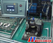
Figure 1 oil pump flexibility test bench
Test mechanism type and component function
Oil pump flexibility test device. It is designed according to the desktop structure and installed on the assembly workbench. It has good stability and flexibility of operation. It includes pneumatic clamping mechanism, gear transmission mechanism, electric torque sensing mechanism and PLC program control system. Part of the composition (as shown in Figure 2 and Figure 3).

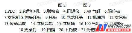
The pneumatic clamping mechanism is: a cylinder with a diameter of 100mm is installed under the platen, a sliding plate is arranged on the gantry, a pallet, a pin, a nylon positioning push-supporting, and an inverted U-shaped limiting plate, and the upper side is also mounted. 40mm diameter cylinder, hook head plate and nylon indenter. The pre-installed oil pump (ie the oil pump whose connection screw has not been fully tightened) is positioned on the pallet, and then the lower cylinder pushes the tested oil pump supported on the pallet below the limit plate and The top is tight, at this time, the hook-shaped pressure plate head of the upper cylinder is slightly pressed to the top of the test pump; then, the micro gear motor and the transmission gear are activated to drive the oil pump to be tested to rotate slowly, and let it be free and stable. Then, the pump cover connecting screw is tightened to the specified torque force, and the normal assembly of the oil pump before the test is completed, the flexibility test can be performed.
The gear transmission mechanism is: a driving gear mounted on the torque meter shaft head, and a bridge gear set mounted on the sliding plate plate fixed on the axle head to bear the transmission function of the oil pump test.
The electric torque sensing mechanism is: under the platen, equipped with a micro gear motor, a coupling bushing, and a torque meter; the coupling sleeve of the micro gear motor shaft head is coupled with the torque meter input shaft, and the torque meter is flip-chip coupled under the frame. The other shaft of the torque meter is equipped with a driving gear to form a transmission system that passes the flexible test transmission system. When the micro geared motor is started, the torque converter is driven by the coupling sleeve, and then the driving gear and the bridge gear are driven to drive the tested oil pump for formal flexibility test; during the test, the torque meter will test the torque force and sense The PLC program controls the system and displays its torque data on the screen. If the flexibility is unqualified, the system will emit a red signal and sound, and the test process will be completed, and the test results will be recorded.
Ductile Iron Wheel
Ductile Iron Wheel,V-Goove Ductile Iron Wheels,Wheels of Ductile Iron
Middle Duty Caster Co., Ltd. , http://www.nbcasters.com