In mechanical motion, the most common transmission for linear motion is the screw drive. The linear motion of the nut is driven by the rotary motion of the screw, which is the most frequently used in our design. This paper discusses the structural design of the sliding helix.
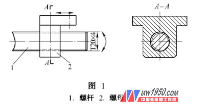
The original design is shown in Figure 1. The rotary motion is converted into a linear motion of the nut by a screw. However, in practical applications, due to the manufacturing error of the screw and the nut, especially when the stroke of the screw is large, and the tail is limited by the conditions, when the support cannot be installed, the movement difficulty or even the stuck phenomenon often occurs. Accelerate thread wear and shorten its life.
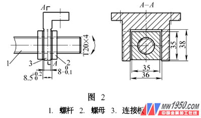
Under this circumstance, we have thought of how to solve the above problems without improving the manufacturing precision of the thread pair. After many design, test and practical applications, we successfully introduced the design concept of the floating nut. As shown in Figure 2, the working principle is introduced. Mill out on the outside of the nut 2  Wide groove, will be thick
  The other connecting plate 3 is inserted into the groove of the nut, and the opening size of the connecting plate should be slightly larger than the size of the nut opening, which is determined by experience. Thus, when the screw rotates to make the nut translate, it will be offset by a small angle of the free swing of the nut, so that the nut can truly exert its function of pushing the axial movement of the load, and the movement accuracy of the connecting plate 3 is determined by its guide rail, The nut can move relatively, we call it a floating nut.
This structure is especially suitable for low-speed, heavy-duty non-precision mechanical transmission, and has been successfully applied to a series of medical lithotripters and various treatment beds produced by our company.
For more articles, please refer to "Mechanical Workers" Cold Processing 2007 No. 1