Third, the choice of agitator
Choosing a reasonable quenching tank agitation method is one of the key elements in the design of large workpiece quenching and cooling system. The purpose is to obtain a suitable liquid flow velocity (ie relative velocity between the quenching medium and the workpiece), flow pattern and turbulent flow region. position. Commonly used mixing methods include compressed air agitation, circulating jet agitation, and propeller agitation. The principle that must be followed when selecting the mixing method is: The flow direction of the quenching medium should be dominated by vertical flow to avoid horizontal flow. This is critical for uniform cooling of shafts or other shaped workpieces with internal bores.
We know that the influence of the flow rate of the quenching medium on its cooling capacity cannot be ignored. Table 1 lists the cooling strength (H) values ​​of various quenching media under varying degrees of agitation.
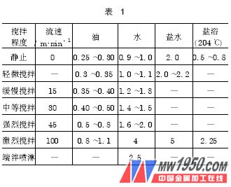
It can be seen from Table 1 that under the condition of intense agitation of ordinary mineral oil, the H value reaches the cooling rate of the still water, which is three times the cooling capacity of the static state. It can be seen that reasonable selection of the stirring mode and stirring intensity of the cooling system can obtain different cooling performances in the same quenching medium, thereby meeting the cooling requirements of different workpieces.
The investment in compressed air agitation is minimal, and proper flow velocity, flow pattern and turbulent zone position can be obtained by proper configuration of the nozzle and injection pressure. The disadvantage is that the formation of quenching medium and air mixing will not only cause uneven cooling of the workpiece, but also accelerate the oxidation rate of the quenching medium (especially quenching oil), and at the same time easily bring in moisture. Therefore, it should be used with caution in quenching and cooling systems using quenching oil.
Recirculating jet agitation is mostly used in deep well quenching tanks. It is one of the more agitating forms, and the jetting force can be obtained from the circulating cooling pump. However, since the injection pressure is required to be high, in order to avoid a large influence on the overall system design, in the deep quenching tank, it is necessary to form a multi-stage relay type agitation while matching the supercharging nozzle. The disadvantage of this type of agitation is that it is limited by the flow rate, the agitation intensity is low, and it is difficult to obtain a strong agitation effect.
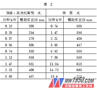
Propeller agitation is the best mixing method for process performance. Under the same installed capacity, the flow rate can reach more than ten times that of jet agitation. With the guide tube and distribution guide plate, the flow pattern and turbulent flow area can be Get very good control. Different diameter propellers and different installation methods consume different power. The corresponding relationship is shown in Table 2 (speed = 420r/min). From the perspective of energy conservation, the use of top-mounted high-efficiency airfoil propellers is the preferred solution for design. In order to obtain as many mixing stages as possible, the agitator should also be capable of variable frequency speed regulation.
Fourth, quenching oil and its temperature control
In the quenching of large workpieces, quenching oil is still the most used quenching medium, and most of them use cold oil quenching oil, the use temperature is between 20 ~ 80 °C. The temperature rise during the use of quenching oil can be calculated as follows:
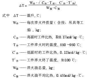
The actual number of quenching oils is calculated according to the maximum quenching of the workpiece and the quenching period of the system, and is generally equipped in a ratio of 8:1. With efficient cooling equipment, this ratio can be reduced to 7:1, and even down to 6:1 with reasonable system design. When designing, the heat exchange capacity of the cooler can be calculated according to the proportion of the quenching oil. There are many types of quenching medium coolers, such as plate type, tube type, coil type, complex wave umbrella type, common air cooling type and vacuum heat pipe air cooling type. According to the cooling method, it can be divided into two categories: water-cooled and air-cooled. In general, water-cooled cooling is more efficient, but the disadvantages are also obvious. First, since the temperature of the cooling water needs to be controlled, it is necessary to establish a sufficiently large cooling pool or use a cooling tower for secondary heat exchange, which increases investment cost and floor space. Secondly, there is a potential danger of oil/water intermixing. , may cause very serious consequences, such as quenching of the workpiece, increased deformation, increased water temperature, vaporization, quenching oil spilling and fire. The vacuum heat pipe air-cooled heat exchanger that emerged in recent years is an ideal cooler. This heat exchanger utilizes the liquid/vapor phase change principle and uses a vacuum heat pipe as a heat transfer medium, which greatly improves the heat exchange efficiency. Practice has proved that the use of vacuum heat pipe air-cooled heat exchanger to control the temperature of quenching oil is very reliable; at the same time, the ratio of cooling capacity to power consumption is only about 100: 5, and the energy saving effect is very obvious. When multiple quenching tanks are equipped with the same quenching oil system, centralized cooling should be used, which also helps to optimize the overall system configuration. In order to prevent mechanical impurities in the quenching oil from clogging the cooler, a filter should be installed between the outlet of the circulating oil pump and the inlet of the cooler.
Five, automatic fire
Automatic fire extinguishing is not difficult to achieve technically, but its importance cannot be ignored. In production practice, it is difficult to avoid the occurrence of an instant open flame (called flash fire) when a large workpiece enters the oil. However, this open flame is maintained for a short period of time, generally not exceeding 10 s, and can be used after all the workpieces enter the quenching oil. Off.
There are three basic conditions for quenching oil fires: the oil temperature exceeds its flash point and reaches the ignition point; there is an open flame; there is air or other oxygen-containing material. Since open flames are difficult to eliminate, quenching oil automatic fire extinguishing systems need to make a fuss about monitoring oil temperature and insulating air. Automatic fire suppression is achieved by timely injection of fire extinguishing gas or other fire extinguishing agent. Since the large workpiece heat treatment workshop is equipped with nitrogen, it is convenient to send nitrogen (no dry powder or other fire extinguishing agent) to the quenching tank, and install a series solenoid valve at the outlet, one of which Controlled by the temperature signal provided by the temperature sensor and controlled by a flame signal provided by the flame detector. This not only ensures the reliability of the fire extinguishing system, but also effectively avoids the waste caused by spraying the fire extinguishing agent during the flashing phase. When the quenching oil is in a fire, the power supply may be cut off. Therefore, the solenoid valve needs to be equipped with an uninterruptible power supply or a bypass manual valve to ensure that the system can still work normally when the power is off.
Conclusion
The design of large workpiece quenching and cooling system is a system engineering, which requires expertise in heat treatment engineering, mechanical engineering and automatic control. By integrating these expertise and advanced design concepts, the system design can meet the production needs, achieving reliable performance, safety, energy saving and environmental protection.
Previous page