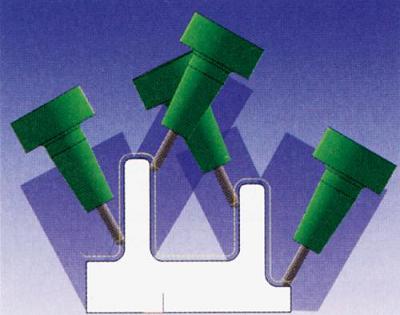
Successful five-axis machining applications are not just about buying a five-axis machining center and some five-axis CAM software. The machining center must be suitable for machining molds. Similarly, CAM software must have five-axis functions and must be suitable for mold processing. The function. The use of short cutting tools is a major feature of five-axis machining. Short tools can significantly reduce tool deviations, resulting in good surface quality, avoiding rework, reducing electrode usage and shortening EDM processing time. When considering five-axis machining, the goal of using a five-axis machining tool is to: complete the machining of the entire workpiece with the shortest cutting tool possible, as well as reduce the programming, clamping and machining time to achieve a more perfect surface quality. . Triaxial and 3+2 axis machining As long as the workpiece cavity is not very deep (relative to the tool diameter), the three-axis tool path (2, 3, 5) is sufficient. If the workpiece cavity is deep and has a very narrow area, it is not enough to use a pure three-axis tool path to complete the finishing. In this case, poor surface quality and longer processing time follow. Figure 1 shows the three-axis tool path. Here, the shortest tool must be long enough to be machined to all areas of the workpiece in the vertical direction. Figure 1 Three-axis machining path (Image courtesy of Sescoi) When using shorter tools, the spindle should be tilted to ensure that special areas of the workpiece can be machined. 3+2 axis machining is generally considered to be a constant angle to the spindle. Complex workpieces may require many oblique views to cover the entire workpiece, but this can result in overlapping tool paths, which increases machining time. In addition, all the oblique views are difficult to accurately combine, so the amount of manual sanding is increased, and the in and out movements are greatly increased, often resulting in surface quality problems and more tool movement. Finally, programming in this way creates mutual interference and is time consuming, and the sum of all views often does not cover the entire geometry. Figure 2 illustrates four workpiece views, but there is still one area in the center of the workpiece that is not covered, and this area still requires an additional oblique view. Figure 2 3+2 axis tool path Next page Here you can find the related products in Ultrasonic Water Meter, we are professional manufacturer of Ultrasonic Water meter,Ultrasonic Water Flow Meter,Portable Water Flow Meter,Octave Ultrasonic Water Meter. We focused on international export product development, production and sales. We have improved quality control processes of Ultrasonic Water Meter to ensure each export qualified product. Ultrasonic Water Meter,Ultrasonic Water Flow Meter,Portable Water Flow Meter,Octave Ultrasonic Water Meter Xi'an Gavin Electronic Technology Co., Ltd , https://www.gaimcmeaso.com
When using five-axis machining, it is necessary to consider the shortest cutting tool to complete the entire mold processing, so as to obtain good surface quality, avoid rework, reduce the use of welding rods, and shorten the processing time of EDM. 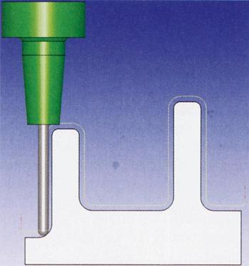
If you want to know more about the products in Ultrasonic Water Meter, please click the product details to view parameters, models, pictures, prices and other information about Ultrasonic Water Meter,Ultrasonic Water Flow Meter,Portable Water Flow Meter,Octave Ultrasonic Water Meter.
Whatever you are a group or individual, we will do our best to provide you with accurate and comprehensive message about Ultrasonic Water Meter!